Layout scheme of gas detector in storage and loading and unloading area of chemical plant
The storage and loading and unloading area of chemical plant is a high-risk link with concentrated materials, large liquidity and easy leakage. For storage tank areas, warehouses and loading and unloading platforms, the layout of gas detectors should strictly follow the principle of “source coverage, density stratification and wind direction priority”. Based on relevant safety regulations, this scheme provides specific layout strategies for different scenarios.
Storage tank area: grid monitoring in fire dike
The storage tank area is usually located outdoors with a wide space, but it is easy to accumulate leakage gas in the fire dike. For Class A, B and A liquid and liquefied hydrocarbon storage tanks, combustible gas detection points must be set in the fire dike. In the plane layout, the detector should cover high-frequency leakage sources such as drain, water cut, sampling port and inlet and outlet valve group, and the horizontal distance between the detector and these release sources should not be greater than 15m. If the circumference of the storage tank group is long, it should be arranged in a grid according to the standard of setting one tank every 20 to 30 meters.
In the vertical height, the installation position should be determined according to the material characteristics. If the stored materials are heavier than air after gasification (such as liquefied petroleum gas and benzene), the detector should be installed at a distance of 0.3 m to 0.6 m from the floor, focusing on monitoring the low-lying water accumulation or drainage ditch in the fire dike, because these positions are “traps” for heavy gas accumulation. If the stored materials are lighter than air (such as liquid ammonia and hydrogen), the detector should be installed 0.5 to 2 meters above the exhaust valve or breathing valve at the top of the storage tank, or directly installed at the highest point at the top of the storage tank to capture the rising gas cloud.
Loading and unloading platform: accurate capture of flow source
Railway and truck loading and unloading platform are dynamic working areas, and the joint between crane pipe and tanker is the main source of leakage release. For the railway loading and unloading platform, a detector should be set at every other parking space on the ground, and the horizontal distance between the detector and the loading and unloading entrance should not be greater than 15m, so as to ensure the working position of each car is covered. For the truck loading and unloading station, the detector should be arranged near the crane position of the loading and unloading vehicle, and the horizontal distance from the crane position should not be more than 10 meters.
Considering that materials may splash or flow during loading and unloading, if the medium is heavier than air, the detector should be installed near the ground under the loading and unloading arm or crane pipe, and avoid the area where the vehicle tires may be crushed. In the liquefied hydrocarbon filling station, in the closed or semi-closed bottle filling room, the horizontal distance between the detector and the filling port should be controlled within 7.5 meters, and in the case of open-air filling, it should be set on the downwind side.
Between Warehouse and Gas Cylinder: Dead Angle Defense of Indoor Air Flow
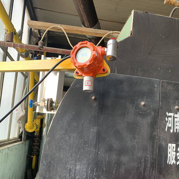
The dangerous chemicals warehouse and the gas cylinder are semi-closed or enclosed spaces, and the air circulation is relatively poor, so gas is easy to accumulate in dead corners. The detectors should be preferentially installed in poorly ventilated areas, doorways or windows and other passages where gas may escape. For warehouses that may leak gases heavier than air (such as liquid chlorine and liquid ammonia cylinders), the detector should be installed at the corner of 0.3m to 0.6m from the ground; If light gas such as hydrogen is stored, it should be installed at the highest point of the roof or under the beam.
In the gas cylinder room, the detector should be installed close to the outlet of the gas cylinder valve, and the distance should not exceed 1 meter. If there is an emergency exhaust fan between gas cylinders, the gas detection and alarm system should be interlocked with the fan. Once the gas concentration exceeds the standard, the fan will be automatically started for forced exhaust.
Environmental factors and installation details
When determining the specific location, we must fully consider the local dominant wind direction. In an open or semi-open place, the detector should be preferentially arranged on the windward side of the minimum frequency wind direction of the release source, or at a position close to the release source on the downwind side (toxic gas is less than 1 meter, combustible gas is less than 5 meters), and the leaked gas is “blown” to the sensor by the airflow.
In addition, the installation location should avoid strong electromagnetic interference, high-temperature heat sources (such as heat tracing pipelines) and places where water drops and oil stains directly drop to prevent sensor poisoning or false alarm. Clear space of not less than 0.3m should be reserved around all detectors to facilitate future calibration and maintenance. Through this three-dimensional and refined arrangement, it can be ensured that the gas leakage in the storage and loading and unloading area is “found early and alerted early”.


 WhatsApp: 008619339980364
 E-mail: contact@hirepsafety.com