Fixed Gas Detector Installation Guide Manual
Foreword
Proper installation is crucial for ensuring that fixed gas detectors accurately and reliably monitor target gases, promptly issue alarms, and protect personnel and property. This guide is specifically designed for the installation principles and procedures of our company’s products.
Pre-Installation Preparations
Personnel Qualification Requirements
Installation personnel must possess professional electrical knowledge, be familiar with the characteristics of flammable, explosive, toxic, and hazardous gases, as well as on-site safety operating procedures. If necessary, they must hold corresponding special operation certificates. Before installation, they must undergo specialized training from the equipment manufacturer to master the device structure, wiring methods, and debugging key points.
Equipment Inspection
1. Verify that the alarm model, detected gas type, and measurement range match the design and procurement requirements.
2. Inspect the device for any external damage and ensure all accessories (sensor, probe, mounting bracket, screws, explosion-proof cover, etc.) are complete.
3. Confirm that the equipment’s explosion-proof rating and protection level meet the requirements of the installation area (e.g., explosion-proof zones, outdoor, humid environments).
Tools and Materials Preparation
1. Core Tools:
Screwdrivers (Phillips and flathead), wire strippers, crimping pliers, electric drill (with matching drill bits), level, tape measure, multimeter, wrench set, insulating tape, cable ties, etc.
2. Auxiliary Materials:
Expansion bolts, mounting brackets (provided with the device or custom-made), flame-retardant wires and cables (meeting on-site explosion-proof rating and transmission distance requirements), sealant, waterproof connectors, etc.
3. Safety Protective Equipment:
Safety helmet, insulated gloves, anti-slip shoes, gas mask (for toxic gas scenarios), explosion-proof flashlight (for explosion-proof areas).
Site Survey and Planning
1. Gas Characteristic Analysis:
Determine the installation height and range based on the density, diffusion rate, and toxicity level of the detected gas. For gases lighter than air (e.g., hydrogen, methane), install the alarm 0.5-2 meters above the leakage source. For gases heavier than air (e.g., Sulfur dioxide,chlorine), install it 0.3-0.6 meters below the leakage source. For gases with similar density to air, install at the same level as the leakage source, within 1 meter.
2. Leakage Source Identification:
Identify potential leak points such as valves, flanges, joints, and tank outlets. The detector should be installed facing the leakage source, 1-3 meters away, avoiding obstructions.
3. Environmental Assessment:
Avoid areas with high temperature, high humidity, strong corrosion, strong electromagnetic interference, severe vibration, or direct sunlight. Keep away from steam sources, oil fumes, and dust-heavy areas. In explosion-proof zones, use equipment and accessories that meet the corresponding explosion-proof rating (e.g., Ex db IIC T6 Gb, Ex db ia IIB T4 Gb). Unauthorized modifications are strictly prohibited.
4. Wiring Layout Planning:
Determine the installation locations of the controller and detector. Plan cable routing paths, avoiding power cables and high-temperature pipelines. Use conduits or cable trays for neat and secure wiring, leaving some slack for maintenance.
Wiring Operation
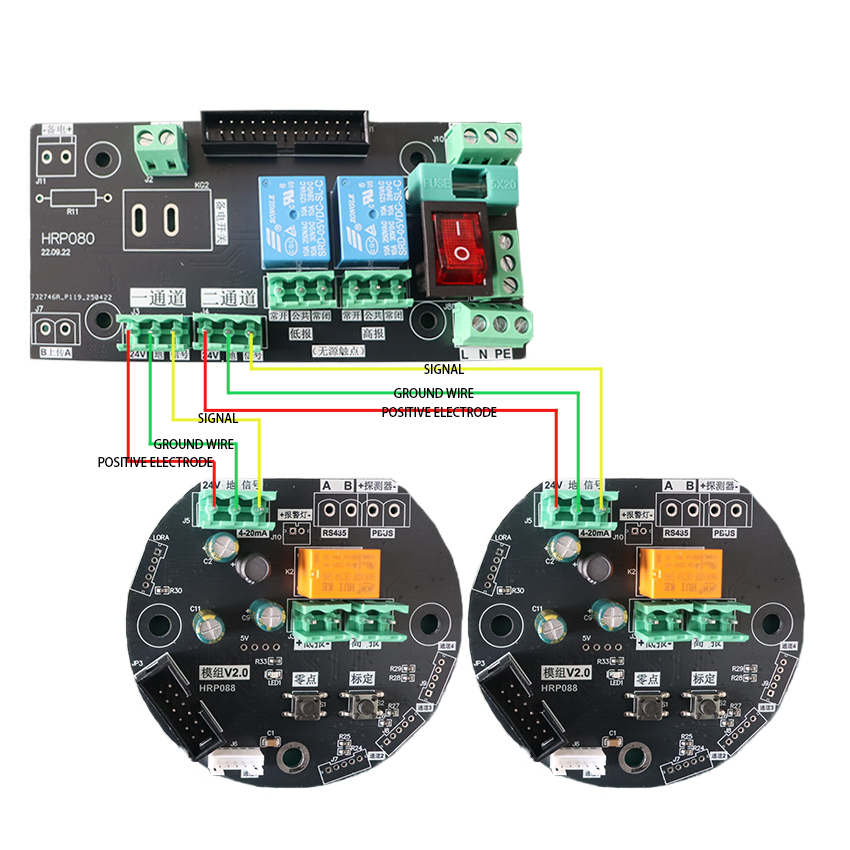
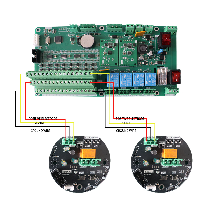
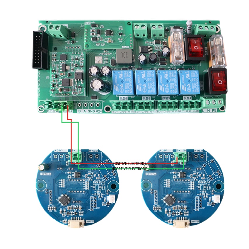
1. Wiring Principles:
Strictly follow the wiring diagram in the product manual. Perform wiring with power off. In explosion-proof areas, wiring must comply with explosion-proof standards. Use flame-retardant, shielded cables. Single cable length should not exceed the product’s specified maximum to avoid signal attenuation.
2. Cable Handling:
Strip the cable’s outer insulation to expose inner conductors (moderate length, avoiding excessive or insufficient exposure). Clean oxidation from conductor surfaces. Connect to the detector and controller terminals according to polarity and signal wire correspondence. After wiring, use crimping pliers to secure connections, ensuring good contact without looseness or poor connections.
3. Insulation and Fixing:
After wiring, wrap terminals with insulating tape for insulation. Neatly arrange cables and secure with cable ties to avoid tension on terminals. After wiring the controller side, verify correctness before closing the cover.
Post-Installation Inspection and Debugging
1. Mechanical Inspection:
Confirm all components are securely installed without looseness, and the housing is properly sealed.
2. Electrical Inspection:
Use a multimeter to check power polarity and voltage for normalcy, and inspect for short circuits or open circuits in the wiring.
3. Power-On Test:
① Turn on the power and observe if the detector indicator lights are normal (typically, a warm-up self-test occurs after power-on).
② After warm-up stabilization (refer to the manual, usually taking minutes to tens of minutes), observe if readings on the controller or display module are within the normal background value range (in clean air).
4. Functional Test (Gas Test):
① Use standard test gas corresponding to the target gas and a compliant test cover to slowly release gas toward the detector sensor.
② Observe if the controller display value steadily rises and triggers audible/visual alarms upon reaching the set low alarm threshold.
③ Record alarm response time and displayed concentration value. After removing the test gas, the value should steadily drop back to the background level.
Never use non-standard gas sources like lighter gas for testing!
5. Parameter Settings:
Set correct parameters on the controller as needed, including range, alarm points (typically low and high alarms), units, etc.
Post-Installation Maintenance and Precautions
Routine Maintenance
1. Regular Cleaning:
Weekly, wipe detector surfaces with a clean, soft cloth to remove dust and oil. Avoid sensor clogging. Power off during cleaning. Never rinse with water or use corrosive solvents.
2. Regular Calibration:
Perform zero and span calibration every 3-6 months based on on-site gas concentration fluctuations and product requirements. Record after calibration to ensure detection accuracy.
3. Fault Troubleshooting:
Monitor device status during routine inspections. If fault alarms, value drift, or unresponsiveness occur, power off promptly and check wiring, sensor, power supply, etc. Contact the manufacturer for repairs if unresolved.
4. Sensor Replacement:
Sensors have a limited lifespan (typically 2-5 years, refer to product manual). Replace with the same model upon expiration. Recalibrate after replacement before use.
Safety Precautions
1.Strictly follow explosion-proof operation regulations during installation and maintenance in explosion-proof areas. Non-explosion-proof tools are prohibited to avoid spark-induced hazards.
2.In toxic, flammable, or explosive gas environments, ventilate the area first and ensure gas concentrations are within safe limits before work. Wear appropriate protective gear and assign a supervisor.
3.Do not disassemble or modify the device during operation. For repairs or part replacement, power off first and allow the device to cool. After repair, ensure proper sealing and compliance with explosion-proof requirements.
4.Avoid exposing detectors to high gas concentrations, severe vibration, or high-temperature shocks to prevent sensor damage and extend device lifespan.
5.Regularly inspect cable lines. Replace if aging, damaged, or exposed to avoid short circuits, leakage, and safety incidents.
This guide is only applicable to the installation of Hirep fixed gas detector alarm products. All liability for equipment failures or safety accidents resulting from non-standard installation, improper maintenance, shall be borne by the relevant responsible parties. It is recommended to consult the equipment manufacturer’s technical personnel before installation to ensure compliance and safety.
Click here to contact us


 WhatsApp: 008619339980364
 E-mail: contact@hirepsafety.com